Basic Eddy Current Testing, Pt 2
Back to the Start ...
· Previous Page ... · Next Page ...
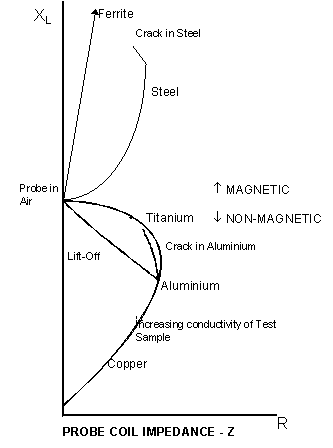
Eddy current responses of a single coil may be conveniently described by reference to the "impedance plane". This is a graphical representation of the complex probe impedance where the abscissa (X value) represents the resistance and the ordinate (Y value) represents the Inductive reactance.
Note that, while the general form of the impedance plane remains the same, the details are unique for a particular probe and frequency.
The display of a typical CRT display eddy current instrument represents a 'window' into the impedance plane, which can be rotated and "zoomed" to suit the needs of the application. For example in the above impedance plane diagram a rotated detail of the "probe on aluminium" area would appear as below:
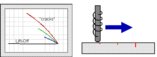
This shows the display when moving over a series of simulated cracks of varying depths Note that, in the example shown both the amplitude and the phase of response from the different sized cracks varies.
Appropriate coil selection is the most important part of solving an eddy current application, no instrument can achieve much if it doesn't get the right signals from the probe.
Coil designs can be split into three main groups:
Surface probes used mostly with the probe axis normal to the surface, in addition to the basic 'pancake' coil this includes pencil probes and special-purpose surface probes such as those used inside a fastener hole.
Encircling coils are normally used for in-line inspection of round products, The product to be tested is inserted though a circular coil.
ID probes are normally used for in-service inspection of heat exchangers. The probe is inserted into the tube. Normally ID probes are wound with the coil axis along the centre of the tube.
These categories are not exhaustive and there are obviously overlaps, for example between non-circumferential wound ID probes and internal surface probes.
To this point we have only discussed eddy current probes consisting on a single coil, These are commonly used in many applications and are commonly known as absolute probes because they give an 'absolute' value of the condition at the test point.
Absolute probes are very good for metal sorting and detection of cracks in many situations, however they are sensitive also to material variations, temperature changes etc.
Another commonly used probe type is the 'differential' probe. This has two sensing elements looking at different areas of the material being tested. The instrument responds to the difference between the eddy current conditions at the two points.
Differential probes are particularly good for detection of small defects, and are relatively unaffected by lift-off (although the sensitivity is reduced in just the same way), temperature changes and (assuming the instrument circuitry operates in a "balanced" configuration) external interference.
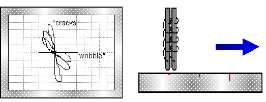
The diagram shows a typical response from a differential probe. Note:
The characteristic "figure of eight" response as first one probe element, then the other, move over the defect. In general the closer the element spacing the wider the "loop" in the signal.
Lift-off should be cancelled out assuming that the probe is perfectly balanced, but there will still be a "wobble" response as the probe is moved and tilted slightly.
Reflection or Driver/pickup probes have a primary winding driven from the oscillator and one or more sensor windings connected to the measurement circuit. Depending on the configuration of the sensor windings reflection probes may give response equivalent to either an absolute or differential probe.
 |
 |
| "Absolute" reflection probe | "Differential" reflection probe |
Main advantages of reflection probes are:
Typical Coil Connections.
Bridge
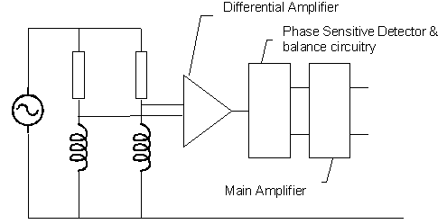
The two coils (Differential or Absolute plus balancing coil) form the 'legs' of a bridge. When the bridge is balanced the measured voltage will be zero, Any change in the condition of either coil will resulted in an unbalanced bridge, the degree of imbalance corresponds to the change in coil impedance.
Driver pickup.
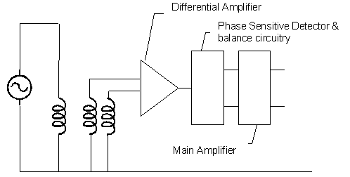
As can be seen the essential elements are the same for a driver/pickup configuration as for a bridge, the necessary changes can be achieved by simple switching or probe connection changes.
Back to the Start · Previous Page · Next Page